Optocoupler Relays vs. Traditional Relays: Which is Best for Your Product?
In the world of circuit design, the choice of “switch” often determines the lifespan, reliability, and dimensions of the entire system. Whether designing precision industrial control boards or consumer electronics, engineers face a classic dilemma: should they choose the mature, cost-effective Electromechanical Relay (EMR), or the high-performance, future-oriented Optocoupler Relay (commonly referred to as PhotoMOS or SSR)?
This article provides a deep dive into the technical differences between the two to help you make the most informed decision for your product selection.
I. Technical DNA: Physical Contacts vs. Photoelectric Conversion
To make the right choice, one must first understand the operating logic of both components.
1. Traditional Electromechanical Relay (EMR)
The working principle of a traditional relay is based on electromagnetic induction. When the coil is energized, it generates a magnetic field that attracts a physical contact to close the circuit. It essentially functions as a physical knife switch driven by electric current.
Keywords: Mechanical movement, physical contact, electromagnetic coil.
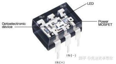
2. Optocoupler Relay (PhotoMOS/Opto-Switch)
Optocoupler relays (such as the SOP-4 packaged devices focused on in your project) belong to the category of Solid State Relays (SSR). They integrate an LED and a light-sensitive power MOSFET. When the input LED emits light, the optical signal passes through an isolation layer to trigger the MOSFET to conduct.
Keywords: Semiconductor switch, optical isolation, no mechanical movement.
II. Core Dimension Comparison: Which is the Performance King?
1. Lifespan and Reliability: The Temptation of Zero Wear
EMR: Because physical contacts exist, every switching action produces a tiny electric arc, leading to contact oxidation or sticking. Mechanical structures also have fatigue limits (typically 100,000 to 1,000,000 cycles).
Optocoupler Relay: Being “solid-state,” there is no mechanical friction or contact wear. Its lifespan is virtually equivalent to that of the semiconductor itself, theoretically allowing for infinite switching cycles. If your product requires high-frequency switching (e.g., several times per second), optocoupler relays are the only viable choice.
2. Response Speed: Milliseconds vs. Microseconds
EMR: Limited by the physical inertia of the metal leaf, switching speeds usually range from 5ms to 15ms.
Optocoupler Relay: Relying on electron migration for switching, speeds can reach the microsecond (µs) level. This speed advantage is critical when cutting off I2C (SDA/SCL) signals or during high-frequency signal transmission.
3. Electromagnetic Interference (EMI) and Acoustic Noise
EMR: These produce a distinct “click-clack” sound during operation. More importantly, the back-EMF from the coil and the contact arcing generate significant EMI, which can cause nearby MCUs to reset or corrupt data.
Optocoupler Relay: Completely silent. Since there are no inductive coils or arcs, they generate almost no EMI, making them ideal for medical devices and audio equipment extremely sensitive to noise.
4. Package Size and Integration
EMR: Even ultra-miniature models have considerable volume and height.
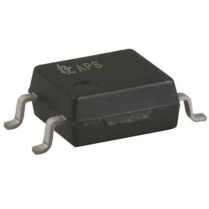
Optocoupler Relay: These can be made extremely compact. For instance, the SOP-4 package occupies only a fraction of the board space of a traditional relay. For modern PCB designs pursuing thinness and miniaturization (such as handheld devices or precision modules), optocoupler relays hold a dominant advantage.
III. Cost and Load: The “Moat” of Traditional Relays
If optocoupler relays are so superior, why haven’t traditional relays been phased out?
High Current Load Capacity: When handling high power and large currents (e.g., industrial motors over 10A or high-power heaters), EMRs offer a massive cost advantage. While high-power SSRs can do the job, their thermal management costs and unit prices increase exponentially.
Surge Resistance: Physical contacts in EMRs are more resilient to instantaneous overvoltage and current surges. In contrast, the semiconductor structure of an optocoupler relay is relatively fragile and more prone to breakdown during extreme power grid fluctuations.
Price Sensitivity: For household appliances with extremely strict cost controls and low switching frequencies (like a basic rice cooker), a cost advantage of just a few cents often ensures the EMR wins.
IV. Application Scenarios: Which Best Fits Your Product?
Scenario A: Industrial Automation & Signal Control (Recommended: Optocoupler Relay)
If you are developing industrial PLCs, I/O modules, or Automated Test Equipment (ATE) that requires frequent signal line switching—or, as in your project, need to cut off 3.3V I2C communication signals (SDA/SCL).
Reason: Ultra-high response speed, zero maintenance, and the tiny SOP-4 package perfectly fit dense PCB layouts.
Scenario B: Power Distribution & High-Power Equipment (Recommended: EMR)
If you are designing 220V AC-powered industrial ovens or high-power Power Distribution Units (PDUs).
Reason: Extremely low contact resistance (reducing heat), resilience to high voltage surges, and high cost-effectiveness.
Scenario C: Medical & Precision Instrumentation (Recommended: Optocoupler Relay)
Reason: Extremely low leakage current and complete electromagnetic silence ensure the accuracy of precision sensor readings.
V. Summary: The “Golden Rules” of Selection
When choosing a relay, ask yourself three questions:
Is the switching frequent? If it exceeds 100 times per day, choose an optocoupler relay.
Is space constrained? If the board is very tight, prioritize the SOP-4 optocoupler relay.
Is the load current massive? If it exceeds several amperes and high-speed switching isn’t required, a traditional relay is more economical.
With advancements in semiconductor technology, the internal resistance of PhotoMOS is continuously decreasing while load capacities are rising. For products striving for high reliability, long life, and a modern feel, the optocoupler relay is increasingly becoming the “standard answer” for engineers.
Expert Tip: In your I2C communication control project, using an optocoupler relay not only achieves physical signal disconnection but also leverages optical isolation to prevent electronic noise crosstalk on the bus. This is not just a component upgrade; it is an evolution in system design thinking.