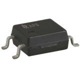
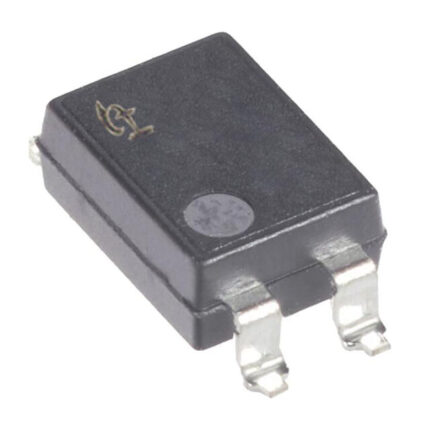
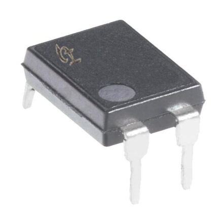
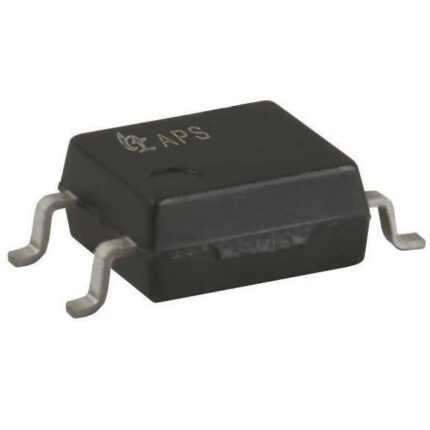
In modern electronic circuit design, the stability and safety of signal transmission have always been core concerns for engineers. With the rapid development of industrial automation, consumer electronics, new energy vehicles, and Internet of Things (IoT) devices, the need for isolation between high and low voltage circuits and reliable transmission of high-frequency signals has become increasingly urgent. The optical coupler (abbreviated as “optocoupler”), as an electronic component that transmits electrical signals using “light” as a medium, has become an indispensable basic device in the field of electronic engineering due to its excellent electrical isolation performance and anti-interference capability.
This article will comprehensively sort out the application scenarios, classification system, as well as the advantages and disadvantages of optical couplers, providing systematic technical information for practitioners and technology enthusiasts in related fields.
1. Core application scenarios of optocoupler
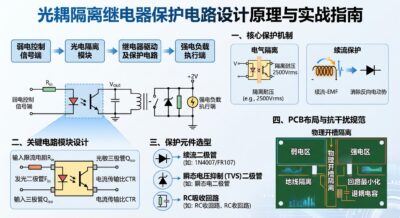
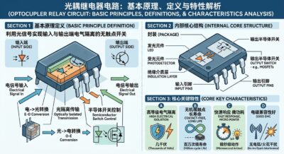
The basic working principle of an optocoupler is to convert an electrical signal into an optical signal through a light-emitting component (such as a light-emitting diode, LED) at the input end. After the optical signal crosses the isolation layer, it is converted back into an electrical signal by a photosensitive component (such as a phototransistor or photodiode) at the receiving end. This “electrical-optical-electrical” conversion mechanism enables complete electrical isolation between the input and output ends, making optocouplers widely used in various complex circuits.
1. Switching power supply and power management system
In flyback switching power supplies, switching adapters, and switching power modules, optocouplers are key components for implementing feedback control loops. The photosensitive transistor at the output end senses changes in the output voltage and safely transmits the feedback signal back to the primary control chip, thereby achieving precise voltage regulation. At the same time, optocouplers can effectively prevent secondary high voltage from flowing backward into the primary control circuit, ensuring the safety of the power supply system.
2. Industrial automation and Programmable Logic Controller (PLC)
The industrial field environment is complex, with strong electromagnetic interference, motor surges, and high-voltage spike pulses. In the digital input/output module of PLC, optocouplers are used to isolate the on-site sensors/actuators from the internal microcontroller (MCU). They not only prevent external high-voltage surges from burning out the core controller but also eliminate ground loop interference, ensuring accurate and precise data acquisition and control instructions.
3. New energy vehicles and battery management system (BMS)
In the power battery management system (BMS), motor controller, and on-board charger (OBC) of electric vehicles (EVs), high-voltage battery packs (typically 400V to 800V) coexist with low-voltage control circuits (12V/24V). Optocouplers are used for communication isolation between high and low voltage domains, voltage/current sampling signal transmission, and fault alarm signal transmission. They are one of the core components ensuring electrical safety in new energy vehicles.
4. Communication network and interface protection
In industrial communication interfaces such as RS-485, RS-232, and CAN bus, long-distance transmission is susceptible to ground potential differences and lightning surge. By introducing high-speed optocouplers into the interface circuit, the ground loop can be cut off and transient high voltage can be absorbed, significantly enhancing the anti-interference capability and reliability of the communication system.
5. Household appliances and smart home
In household appliances such as microwave ovens, induction cookers, air conditioners, and washing machines, optocouplers are commonly used to drive thyristors (TRIACs) or IGBTs, enabling control over heavy loads like AC motors and heating wires. Additionally, optocouplers play a crucial role in AC zero-crossing detection circuits, assisting microprocessors in capturing the mains phase and achieving precise phase control without impact.
II. Systematic classification of optocouplers
To meet the differentiated requirements of different circuits for transmission rate, isolation level, linearity, and load capacity, the industry has introduced various types of optocoupler products. The classification of optocouplers can generally be divided based on dimensions such as output terminal structure, transmission signal type, and response speed.
1. Classification by output terminal device type
Transistor output type optocoupler: The receiving terminal utilizes a phototransistor, making it the most widely used general-purpose optocoupler. It features low cost and simple structure, and is commonly used for general switch control and low-speed signal isolation.
Darlington output type optocoupler: The receiving terminal adopts a Darlington transistor structure, featuring a high current transfer ratio (CTR), which enables it to drive a large output current even with a small input current, but its response speed is relatively slow.
Silicon Controlled Rectifier (SCR/TRIAC) optocoupler: The receiving terminal includes a photosensitive bidirectional or unidirectional silicon controlled rectifier, specifically designed for triggering and controlling AC circuits. It can directly drive high-power silicon controlled rectifiers to achieve strong electrical control.
Integrated circuit (IC) output optocoupler: The receiving terminal integrates complex circuits such as amplifiers and logic gates (e.g., Schmitt triggers), supporting high-speed digital signal transmission (e.g., from 10Mbps to over 50Mbps), and is widely used in high-speed communication and gate driving.
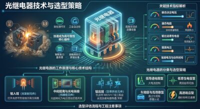
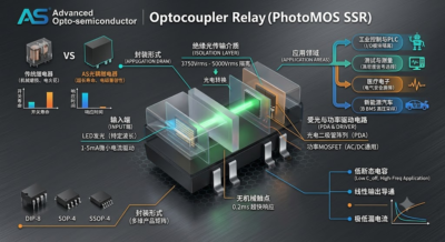
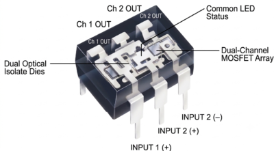
Solid-state relay (SSR) type optocoupler: Combining a photosensitive diode array with a field-effect transistor (MOSFET), it can achieve contactless AC or DC load switching, featuring no mechanical wear and a long lifespan.
2. Classification based on the nature of transmission signals
Digital (logic) optocoupler: used for transmitting switch signals or digital pulse signals. Its output typically presents logic high/low voltage levels, with a fast response speed, and is mainly used for digital interface isolation and pulse driving.
Linear optocoupler: used for transmitting continuously changing analog signals (such as voltage and current sampling values). Linear optocouplers typically employ dual photosensitive receiving elements for differential compensation internally, overcoming the nonlinear current transmission ratio of ordinary optocouplers and ensuring high-fidelity signal transmission.
3. Classification by transmission rate
Low-speed optocoupler: With a transmission rate typically below tens of kilohertz (kHz), representative models such as the commonly seen PC817 are suitable for scenarios where speed requirements are not high, such as power supply feedback and switch control.
High-speed optocoupler: With a transmission rate ranging from 1Mbps to 50Mbps or even higher (such as the 6N137 series), it internally employs a PIN photodiode and a high-speed amplification circuit, making it suitable for high-speed data bus and high-frequency PWM drive signal transmission.
III. Comprehensive evaluation of the advantages and disadvantages of optocouplers
In the design of electronic systems, selecting an optocoupler solution requires a comprehensive trade-off between its technical advantages and physical limitations.
(1) Core advantages of optocoupler
Excellent high-voltage electrical isolation performance
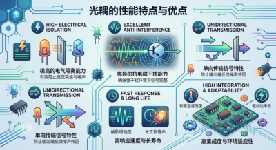
Optocouplers achieve signal bridging through optical media, with no direct electrical connection between the input and output terminals. Their insulation withstand voltage typically ranges from 2500Vrms to over 5000Vrms, effectively protecting against high-voltage surges and spike pulses of thousands of volts, ensuring the safety of low-voltage control terminals and personnel.
Strong anti-electromagnetic interference and ability to cut off ground loops
Since the transmission medium is light, optocouplers are insensitive to external electromagnetic interference (EMI) and radio frequency interference (RFI). At the same time, optocouplers completely cut off the ground connection between the input and output terminals, effectively eliminating common-mode interference and ground loop noise caused by ground potential differences.
Unidirectional signal transmission to prevent signal backflow
Optical signals can only be transmitted unidirectionally from the light-emitting side to the light-sensitive side, and noise or high-voltage fluctuations at the output end cannot be conducted back to the input end, thus exhibiting a natural unidirectional buffering and isolation effect.
No mechanical contacts and long working life
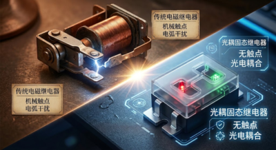
Compared to traditional electromagnetic relays, optocouplers are pure solid-state electronic devices, free from internal mechanical wear and contact oxidation issues. They exhibit characteristics such as noiselessness, sparklessness, shock resistance, and an exceptionally long operational lifespan.
(II) Limitations and design challenges of optocoupler
Optical attenuation and temperature drift of current transfer ratio (CTR)
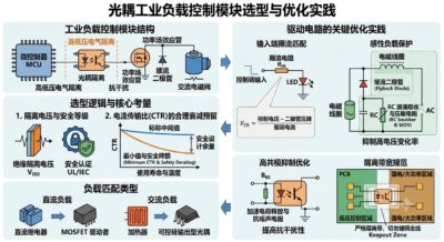
The current transfer ratio (CTR, which represents the ratio of output current to input current) is a crucial parameter of optocouplers. However, the luminous efficiency of light-emitting diodes (LEDs) gradually decreases with increasing usage time (i.e., light decay), and CTR is highly sensitive to temperature variations. Designers must allocate sufficient gain margin during circuit design; otherwise, it may lead to functional failure of the device during long-term operation or in high and low temperature environments.
The transmission rate is limited
Limited by the response time of light-emitting diodes and the influence of photosensitive junction capacitance, the transmission rate of ordinary optocouplers is relatively slow. Although high-speed optocouplers can achieve tens of megabits per second, compared to capacitive isolators or magnetic isolators (which can reach hundreds of megabits per second), optocouplers still present certain bottlenecks in high-capacity and high-speed data transmission.
The power consumption is relatively high
In order to maintain the normal conduction and signal transmission of the optocoupler, the light-emitting diode (LED) at the input terminal typically requires a driving current of several milliamps (mA). In multi-channel or low-power battery-powered devices, the cumulative power consumption of the optocoupler may pose a challenge for overall power consumption control.
Volume and integration constraints
Compared to modern digital isolation chips, traditional optocouplers, which consist of two physical chips for light emission and reception as well as encapsulated optical glue, are difficult to achieve ultra-large-scale multi-channel integration and occupy a relatively large area on the PCB board.
IV. Summary and Outlook
Optocouplers, leveraging their unique “optical isolation” mechanism, exhibit irreplaceable value in terms of safety, anti-interference, and reliability. Whether in traditional switching power supplies, industrial control, or the booming fields of new energy vehicles and photovoltaic energy storage, optocouplers remain the cornerstone for building highly reliable electronic systems.
Despite facing competition from digital isolators (such as capacitive isolation and magnetic isolation technologies) in terms of speed and power consumption, optocoupler technology continues to evolve. The successive emergence of modern high-precision linear optocouplers, high-voltage optoelectronic relays, and automotive-grade high-speed optocouplers has further expanded its application boundaries. For electronic designers, a deep understanding of the classification characteristics, application environments, and key indicators such as CTR attenuation of optocouplers, combined with specific technical requirements for reasonable selection, is crucial to maximizing their performance and enhancing the overall reliability of products.