Types of Optocouplers: Selection and Replacement
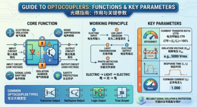
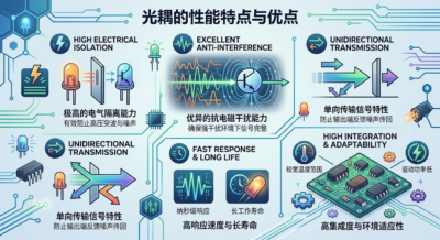
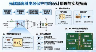
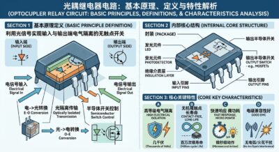
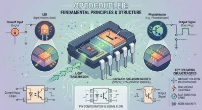
An optocoupler (or optoisolator) is an electronic component that transmits electrical signals via optical signals. It provides electrical isolation between input and output circuits, effectively protecting low-voltage control circuits from high-voltage or high-current surges, while offering advantages such as strong electromagnetic interference (EMI) immunity and stable signal transmission. Optocouplers serve as fundamental components playing a crucial role in fields ranging from industrial automation and consumer electronics to power management and communication equipment. A deep understanding of optocoupler types and a mastery of sound selection and replacement principles are essential for electronic engineers and hardware developers.
I. Classification of Optocoupler Types
Optocouplers come in a wide variety of types; based on internal structure, the type of photosensitive element, and application scenarios, they can be categorized into the following main groups:
1. Transistor-Output Optocouplers
Transistor-output optocouplers are the most common and basic type. Internally, they typically feature a light-emitting diode (LED) as the light source and a phototransistor as the light-receiving element. When current flows through the input, the LED emits light, causing the phototransistor to conduct. These optocouplers feature a simple structure and low cost, making them widely used for switching signal isolation, low-speed data transmission, and power supply feedback circuits.
2. Thyristor-Output Optocouplers
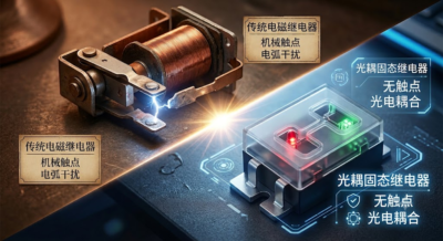
Thyristor-output optocouplers utilize a photosensitive thyristor element at the receiving end. They are classified into bidirectional thyristor (TRIAC) optocouplers and unidirectional thyristor (SCR) optocouplers, primarily used in control circuits for AC loads. These optocouplers establish a safe isolation barrier between low-voltage DC control signals and high-voltage AC loads, finding common application in motor drives, solid-state relays, and home appliance control systems.
3. High-Speed Optocouplers
Standard transistor optocouplers are unsuitable for high-frequency signal transmission due to their relatively slow response speeds. High-speed optocouplers integrate a highly sensitive photodiode and high-speed amplification/drive circuitry, enabling transmission rates ranging from several megabits to tens of megabits per second. These devices are primarily used for digital communication interfaces, industrial bus isolation, and the isolated transmission of pulse-width modulation (PWM) signals.
4. Linear Optocouplers
Traditional optocouplers exhibit a non-linear relationship between output current and input current, making them suitable mainly for isolating digital (on/off) signals. In contrast, linear optocouplers employ specialized optical and circuit designs that allow the output signal to linearly replicate the amplitude variations of the input signal. Designed specifically for analog signal isolation, they are widely used in precision voltage sensing, current sampling, and medical electronic equipment.
5. Darlington Output Optocouplers
Darlington optocouplers utilize a Darlington transistor structure at the receiver end. The advantage of this configuration is an extremely high current transfer ratio (CTR), allowing a small input current to drive a load requiring a much larger current. However, this comes at the cost of relatively slow switching response speeds; consequently, they are typically suited for applications requiring high drive currents but where speed is not a critical requirement.
II. Principles and Key Factors for Optocoupler Selection
Proper selection of an optocoupler during circuit design is essential to ensuring system reliability and meeting performance specifications. The following key parameters and factors should be prioritized during selection:
1. Current Transfer Ratio (CTR)
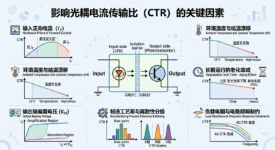
The current transfer ratio (CTR) is one of the most critical parameters of an optocoupler; it represents the ratio of output current to input current, typically expressed as a percentage. The CTR directly determines the optocoupler’s driving capability. An excessively low CTR results in insufficient drive capability, while an excessively high CTR may lead to saturation delay. Additionally, the CTR degrades over time and with temperature fluctuations, so sufficient design margin must be allowed.
2. Isolation Voltage and Safety Standards
Isolation voltage indicates the maximum voltage difference that the optocoupler can withstand between its input and output terminals. Products must be selected to meet the safety standards relevant to the specific application environment. Applications in industrial settings and high-voltage power supplies typically require isolation voltage ratings of several kilovolts or higher. In addition to isolation voltage, physical parameters such as creepage distance and clearance must also be considered.
3. Operating Speed and Response Time
Select an optocoupler with an appropriate speed based on the signal transmission frequency of the circuit. For standard on/off (switching) control, a standard optocoupler with millisecond or microsecond response times is sufficient; however, for high-frequency communication, digital signal transmission, or rapid control applications, a high-speed optocoupler with minimal propagation delay is essential to prevent signal distortion.
4. Linearity and Accuracy
When transmitting analog signals, a linear optocoupler must be selected, with particular attention paid to linearity error, common-mode rejection ratio (CMRR), and temperature drift characteristics. Good thermal stability ensures that high transmission accuracy is maintained across varying ambient temperatures.
5. Package Type and Thermal Dissipation
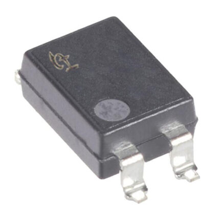
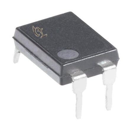
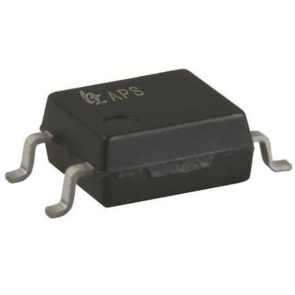
Select an optocoupler package—such as Surface Mount Technology (SMT) or Dual In-line Package (DIP)—that suits the circuit board’s space constraints and assembly process. Additionally, evaluate the operating temperature range to ensure the optocoupler functions reliably under high-temperature conditions.
III. Principles and Precautions for Optocoupler Replacement
During maintenance, supply chain substitutions, or cost-reduction initiatives, it is often necessary to replace an existing optocoupler with a different model. This process involves more than a simple part-number cross-reference; strict technical specifications must be followed:
1. Core Electrical Parameters Must Match or Exceed the Original Model
When replacing a component, ensuring the consistency of key parameters is paramount:
Isolation Voltage: The isolation voltage rating of the new optocoupler must be equal to or higher than that of the original; safety standards must never be compromised.
Current Transfer Ratio (CTR): The CTR range of the new optocoupler should align as closely as possible with the original model. Significant discrepancies may result in circuit malfunction or sluggish response times.
Operating Voltage and Current: Parameters such as maximum input forward current, output voltage rating, and maximum output current must meet the circuit’s actual operational limits.2. Strict Alignment of Function and Type
Different types of optocouplers must never be used interchangeably. For instance, a standard transistor-output optocoupler cannot replace a thyristor-output optocoupler, nor can a standard low-speed optocoupler directly replace a high-speed one. Using a low-speed optocoupler in a high-speed data transmission circuit would cause severe signal distortion, rendering the system unable to communicate.
3. Compatibility of Pin Definitions and Packaging
At the physical level, the pinout of the replacement component must match that of the original component exactly. If the package differs or pin functions do not align, direct soldering onto the existing circuit board will not be possible. For surface-mount components, it is also necessary to verify that the pin pitch and physical dimensions comply with layout requirements.
4. Consideration of Aging and Environmental Adaptability
The light-emitting diode (LED) within an optocoupler experiences a decline in luminous efficiency over time—a phenomenon known as light output degradation. When selecting a replacement, it is advisable to prioritize products with stable quality, strong resistance to degradation, and a wide operating temperature range to extend the service life of the entire device.
5. On-Board Verification and Practical Testing
Theoretical parameter matching cannot fully replace actual circuit testing. Before proceeding with mass replacement, sample soldering and rigorous performance testing are essential. These tests should include high-temperature/low-voltage testing, high/low-temperature cycling, signal waveform measurement, and long-term full-load operation testing to ensure the system’s stability and compatibility after the replacement.
As critical components for achieving electrical isolation and signal transmission, the selection and replacement of optocouplers require a rigorous technical approach. By thoroughly understanding the structural characteristics of various optocouplers, carefully comparing key parameters against actual application scenarios, and adhering to strict verification procedures, one can effectively enhance the overall reliability of electronic products and ensure the long-term, stable operation of circuit systems.
That concludes this article. If you found this information helpful, please continue to follow our website (https://www.a-semi.com) and our WeChat official account, “Advanced Opto-Semiconductor” (先进光半导体), for more news, updates, and educational content. Copyright Notice: Some articles and information are sourced from the internet or user submissions. This website is responsible only for the organization, formatting, and editing of the content. These materials are published to share information and do not imply endorsement of the views expressed or verification of the content’s accuracy. If any articles or submitted content raise copyright or related issues, authors are requested to contact us promptly so that we may address the matter as soon as possible.